In order to satisfy the customer at all times, a product must meet the functional goals that are expected of it. These goals must be met through a diligently implemented product design. One cannot bank upon expert craftsmanship to deliver quality. Quality must be built into the design. In this article we are going to review important methods of designing with geometric tolerances. We will understand how to evaluate the combined effects of size tolerances and geometric tolerances and deliver functional goals in the products we design.
Geometric Tolerances
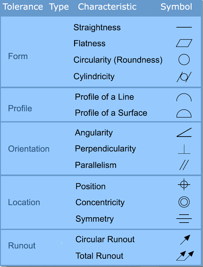
Traditionally, designing has been done assigning dimensions of size and tolerances on size. The design intent cannot however be fully expressed by size tolerances alone. Geometric tolerances are required to define the design completely. The tolerances shown on the adjoining table are defined by the geometric dimensioning & tolerancing standard (ASME Y14.5M -1994).
Tolerances on Size - Maximum Material Condition and Least Material Condition
Every feature that has a size associated with is termed as a feature of size. A hole size is described by its diameter, a slot size is described by its width and depth and a pin size is described by its diameter. A Hole, a slot and a pin are thus features of size.
Let us define two terms for features of size; the Maximum Material Condition (MMC) and the Least Material Condition (LMC).
Maximum Material Condition is defined as that limit of size of a feature where the maximum amount of material is retained on the work-piece. Least Material Condition is defined as that limit of size where the least amount of material is retained on the work-piece.
For a shaft feature, within the tolerance of size:
The largest diameter shaft has the maximum material, and hence is at MMC.
The smallest diameter shaft has the least material, and hence is at LMC.
For a hole feature, within the tolerance of size
The smallest diameter hole has the maximum material, and hence is at MMC
The largest diameter hole as the least material, and hence is at LMC
The figures below illustrates MMC and LMC definitions.
Tolerance on position
The figure below illustrates the variation in the feature caused by the tolerance of position.
A feature is subjected to two types of tolerances, tolerance of size and the tolerance of position. The combined effect of both the tolerances needs to be evaluated to determine the total variation in the feature.
Designing for functional assembly of mating components
Let us study an example of two features, a pin and a hole, that need to go in a functional assembly. The following facts need to be taken into account to design for functional assembly.
The pin is subject to variation of size as well as variation in position within the specified tolerances.
The hole is subject to variation of size as well as variation in position within the specified tolerances.
The hole feature component and the shaft feature component are going to be mass produced at different times and by different manufacturers. They will not be produced in pairs that will assemble. Selective assembly is not desired.
Dimensions and tolerances on the mating features need to be assigned in such a way that functional assembly of the two features will happen even if both the features go to their extreme limits of tolerances.
In order to ensure a functional assembly, the combined impact of all tolerances on a feature needs to be evaluated. The combined impact of all tolerances on a feature will show up as a worst-case envelope that will always contain the feature geometry.
The example below illustrates this evaluation.
Worst-case envelope for a pin feature- The Virtual Condition
Let us take the example of a pin that is subjected to a tolerance of size as well as to a tolerance of position.
If this pin needs to assemble into a mating part, we must assure ourselves that the mating part never interferes with the pin material. A worst-case boundary of the pin that will be formed by the extreme size and all positions within the tolerance must be evaluated.
Looking at the size first, we know that the largest size pin, that is the MMC pin will lead to the worst-case envelope. We thus consider the MMC (diameter 18.2) pin for the purpose of the evaluation of he worst-case envelope.
Next we look at the variation induced by the tolerance of position. The pin can shift from its basic position by 0.2 in any radially outward direction. Since in mass production we cannot predict which direction it will shift, we account for all the possible shifts, and expand the worst-case envelope by 0.2 radially and 0.4 diametrally. The adjacent figure shows this evaluation.
This worst-case envelope is called the virtual condition of the pin. The MMC symbol written with the position tolerance indicates that a Virtual Condition is defined for the pin and that it is calculated with the MMC limit as discussed above.
The MMC Virtual Condition is evaluated when the designer's intent is to assure a functional assembly under all circumstances of size and position.
Worst-case envelope for a hole feature- The Virtual Condition
Let us next look at an example of a hole that is subjected to a tolerance of size as well as to a tolerance of position.
If this hole needs to assemble into a mating part, we must assure ourselves that the mating part never interferes with the walls that form the hole feature. A worst-case boundary of the hole that will be formed by the extreme feature size and all positions within the tolerance must be evaluated. Such an boundary will be an inside envelope for a hole and will signify the guaranteed clear opening left by the hole feature around the basic position.
Looking at the size first, we know that the smallest size hole, that is the MMC hole will offer most resistance to assembly and will lead to the worst-case envelope. We thus consider the MMC (diameter 21.7) hole for the purpose of the worst-case envelope evaluation.
Next we look at the variation allowed by the tolerance of position. The hole can shift from its basic position by 0.3 in any radially outward direction. The wall on the diametrally opposite side of the shift will encroach in the clear opening by a magnitude equal to the shift. Since in mass production we cannot predict which direction it will shift, we account for all the possible shifts, and reduce the worst-case envelope by 0.3 radially and 0.6 diametrally. The figure below shows this evaluation.
This worst-case envelope is called the virtual condition of the hole. It signifies the guaranteed clear opening left by the hole in spite of all the tolerances acting upon it. The MMC symbol written with the position tolerance indicates that a Virtual Condition is defined for the hole and that it is calculated with the MMC limit as discussed above. The MMC Virtual Condition is evaluated when the designer's intent is to assure a functional assembly under all circumstances of size and position.
Assuring functional assembly through matching virtual conditions
If we want that both the features must functionally assemble together under all circumstances, we must ensure through design calculations that the MMC Virtual condition of the Hole is equal in size or larger than the MMC Virtual Condition of the Pin.
The assembly will thus come about as shown in the adjacent figure.
Once design tolerances for the components are assigned as shown above, the functional assembly will be assured. It will not be necessary to pick and choose component pairs that assemble, and selective assembly will thus be avoided. The manufacturers of mating components need not coordinate closely with the designer or with each other. They need to simply follow specified tolerances. The function will be assured through a proper and diligently implemented design.
The LMC Virtual Condition - Protecting wall thickness, maintaining spacing between features
Let us now address another goal through design using GD&T and virtual conditions. The adjacent figure shows an array of holes figured on a metal plate. Each hole is assigned a dimension and a tolerance of size, as well as a tolerance of position. The goal here is to protect the spacing between the holes so that the wall between them does not become too thin.
Here you will notice a LMC symbol next to the geometric tolerance. It indicates that a Virtual Condition is defined, but this time it is defined with the LMC limit.
The example above is used to illustrate the LMC Virtual Condition calculations.
Focusing on the variation on account of size, we can observe that the wall thickness becomes critical when each one of the holes becomes largest within the tolerance of size (dia. 25.3), leading to their LMC.
Further, the holes can shift in every radially outward direction by 0.3. The holes shifting towards each other will lead to a further reduction in the wall thickness. As seen earlier the virtual condition must be evaluated as expanding and reducing envelopes.
The LMC Virtual Condition thus provides the basis of calculations for assuring feature separation and assuring wall thickness protection.
More on Designing with GD&T
The practice of GD&T offers a hoard of other principles for better design. An important principle among these is that of bonus tolerance; where the tolerance of size can be traded off with a geometric tolerance, making the tolerance scheme more flexible and lower in cost. We will visit this topic in a subsequent article on GD&T practice.
In conclusion
The definition of Virtual Condition envelopes in Geometric Tolerancing helps us design products that satisfy function and fit. This is delivered through diligent design calculations that evaluate the combined impact of the several tolerances acting on features.
References:
ASME National Standard- Dimensioning & Tolerancing- ASME Y14.5M- 1994 published by American Society of Mechanical Engineers
Author: Ravindra Khare
Symphony Technologies Pvt. Ltd.,
B-4, Saket, Vidnyan Nagar, Bawdhan,
Pune 411 021, INDIA
Published: November 2008
Ravindra Khare is a Founder and Director of Symphony Technologies. He is a qualified Mechanical and Industrial Engineer and a keen student of Quality & Productivity Technology for the past 25 years.
Designers need to perform Dimensional Variation Analysis (Tolerance Stack up Analysis). Variation caused by traditional coordinate tolerances is easy to understand. However, understanding variation caused by GD&T tolerances can be tricky.
This DVA Guide will help you visualize and evaluate tolerance stacks, and make your designs more predictable.
The FREE GD&T Symbol Application Guide is a ready reference that guides you about how to express tolerances in GD&T. It discusses the correct syntax for using the 14 Geometric Tolerances and also for using Datums for various features that you encounter in GD&T.


 button provided with each animation to run it.